Overall UltimateL39 Engine Package Creation Process
Email Questions or
Comments
Here is a simplified bullet point type description of the UltimateL39
creation process.
For the first few conversions, we will be supplying completed motor
assemblies. This is done to control quality and to fully vet the build up
process so that others can reproduce the effort with great quality. The
assembly is based on a motor that was run on the pylon, comes with a Honeywell
E-Engine data log of the power assurance run and all appropriate log book
entries inclusive of gearbox pressure measurements during the power assurance
run. Nothing is ever guaranteed when purchasing a used engine but we do
our best to properly vet candidates before purchasing. Prior to
evaluation, we do an AD compliance analysis and a cycle life limited component
(mostly disks) analysis to make sure the motor is airworthy and has sufficient
disk cycles remaining to be of value. Our current Approved Inspection
Programs (for the two already issued) allow for hot section on condition but we
must still comply with certified limits on cycles and Core Zone Inspection - CZI
(better known as compressor overhaul). Alternatively, we will be working
with shops to aid and help train personnel on building up motor assemblies as
opposed to building them up ourselves.
The motor assembly is complete from carbon composite inlet to 731-3 motor to
carbon composite fan duct to exhaust exit tube to exhaust exit cone. All
flow path cross sections from type certified installations have been faithfully
retained insuring proper engine performance and efficiency. The assembly
includes front and rear motor mounts installed along with throttle bell crank
and fuel control link. Turbo Cooler plumbing is provided in addition to
the adapter to permit mounting the customer supplied AI-25's bleed air valve to the Turbo Cooler's
air cleaner. The DEEC and Honeywell produced DEEC to engine harness is
supplied with related schematic documentation.
The above engine assembly will literally roll on the existing unmodified L39
engine rails right into place using the original front and rear motor mount
facilities with only one modification. The TFE731-3 motor has a larger fan
than the AI-25. We accommodate this by producing a tapered inlet which
expands the L39s "Y" ducting out to the 731-3's inlet diameter. This cone
is larger in diameter where it passes though the engine firewall than the AI-25
inlet tube and thus the AI-25 inlet tube support flange on the engine to RAT bay
fire wall must be removed. The inward facing lip which has the nut plates
(used by the before mentioned tube support flange) must be trimmed off and a
silicone rubber u-channel protector placed over the sheet metal edge. The
forward facing portion of the firewall pass though remains thus its strength
stays intact. The tail is then rolled on and appropriate adjustments to
rear motor height are made so that the exit cone is centered in the tail exit.
The ACM (Turbo Cooler) bleed air valve (AI-25 part supplied by the customer) is installed on the air cleaner using the
supplied mount then the supplied engine to bleed air valve tubing is installed
to complete the AC and cabin pressurization circuit.
Starter/Generator and engine instruments are the responsibility of the
installer. Reference schematics for the Starter/Generator are supplied
using standard business jet components (main contactor, start contactor, reverse
current relay, feeder protection and Generator Control Unit or GCU).
Installs to date have used the Garmin G3X package for engine instrumentation.
The engine interface module can connect directly with most of the original
TFE731-3 sensors like Oil Temperature, Fuel Pressure Switch, Oil Pressure
Switch, turbine interstage temperature (TIT K thermocouple) and the like.
Where original engine sensors are not compatible with modern experimental
avionics, custom or bespoke sensors or signal conditioning is provided.
These include Oil Pressure, Fuel Flow and signal conditioning for the N1 and N2
monopoles so as to provide conditioned and reduced frequency waveforms which the
G3X (and other) systems will accept. HP/LB bleed air temperature and
pressure sensors are provided. The fire detection loop on the type
certified installation is retained and schematic documentation is provided for
generating proper cockpit test/indication.
The TFE731-3 package described above provides about 25% of the performance
increase that is the UltimateL39. This is my estimate only and not based on any
hard facts. The remaining 75% comes from weight reduction which can only
be realistically achieved with the TFE731-3 engine conversion. This is not
an exhaustive list but here are some of the changes that must be made to achieve
maximum weight reduction. Remove all remnants of the AI-25, engine/rat bay
harnesses, sapphire and supporting elements, RAT, all cockpit wiring paring down
those harnesses that contain support for the ACM, flaps, gear and trim systems.
Replace ejection seats with carbon/composite seats. Remove all O2 and
Nitrogen components. Canopy seals and hydraulic reservoir can be
pressurized by a regulator off the HP/LP ACM supply line. O2 for cross
country and racing is by a pilot carried aboard pulse demand system. Wing
tip tanks are removed along with all their associated wing plumbing. We
produced very small profiled wing end caps with or without integral Aero LEDs NSP lighting
that weight but a few pounds each but many other wing tip designs are available
from other vendors (but they are HEAVY). The effort involved here is
significant but the end result is stellar.
In short, you can do the engine conversion and get some improvement but, to
get the performance of the UltimateL39, you must remove the weight and get the
plane to around 6,000 lbs empty. Anything short of this is simply not
fully doing the job.
The package described above comes with reference schematic documentation from
our first UltimateL39 which includes an electro-hydraulic pump pack. We also
provide our Inspection Program which has been accepted by the FAA on two
previous occasions and supporting engineering documentation covering analysis of
the front and rear motor mounts and other major modifications required to
generate an UltimateL39. These documents are provided in an engineering report
assigned to each aircraft serial number and bearing a PE stamp. In addition to
being used for issuing an Experimental Airworthiness, these documents have been
submitted, along with relevant flight test data, to authorities for inclusion at
the Reno Air Races.
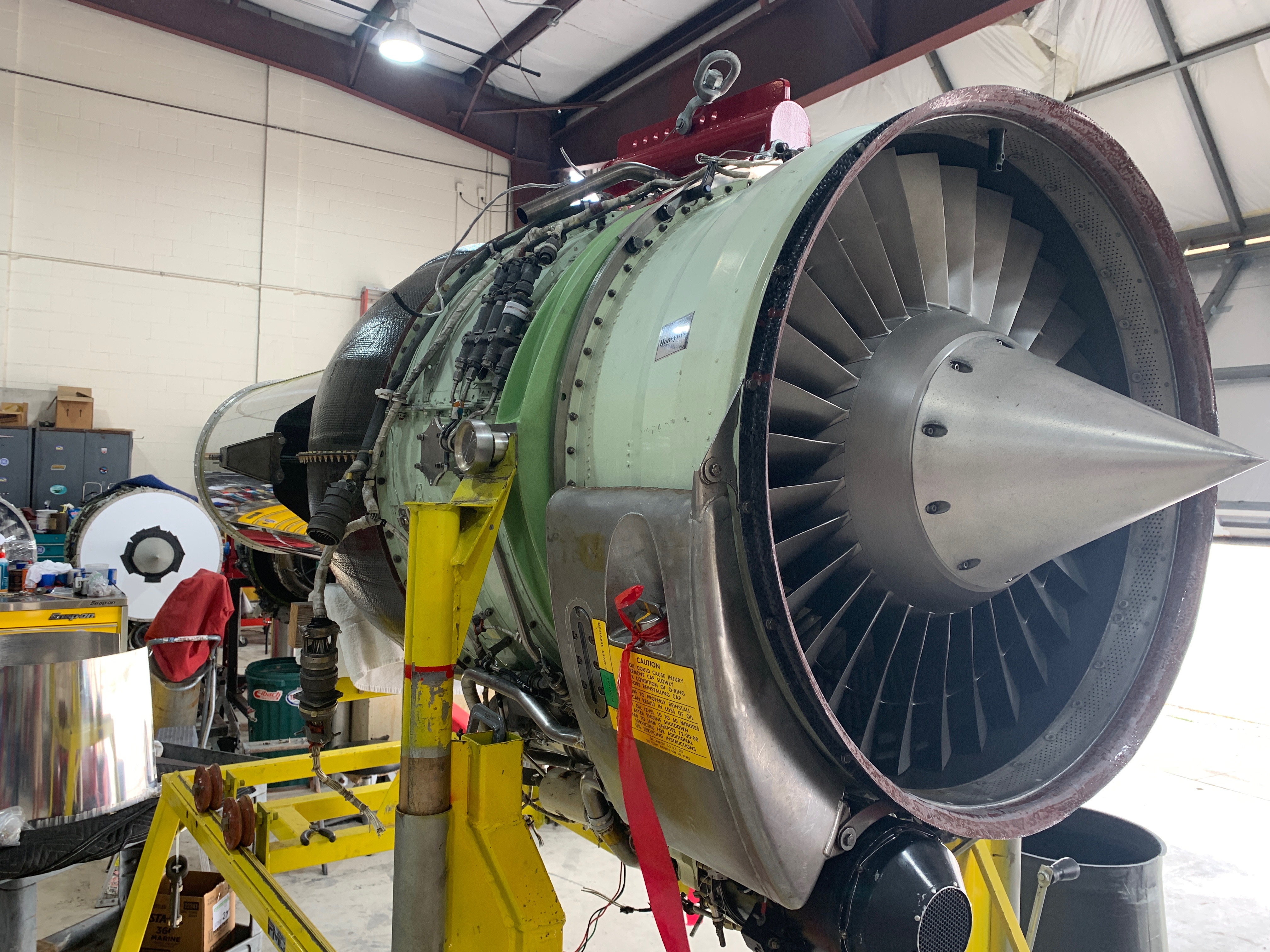
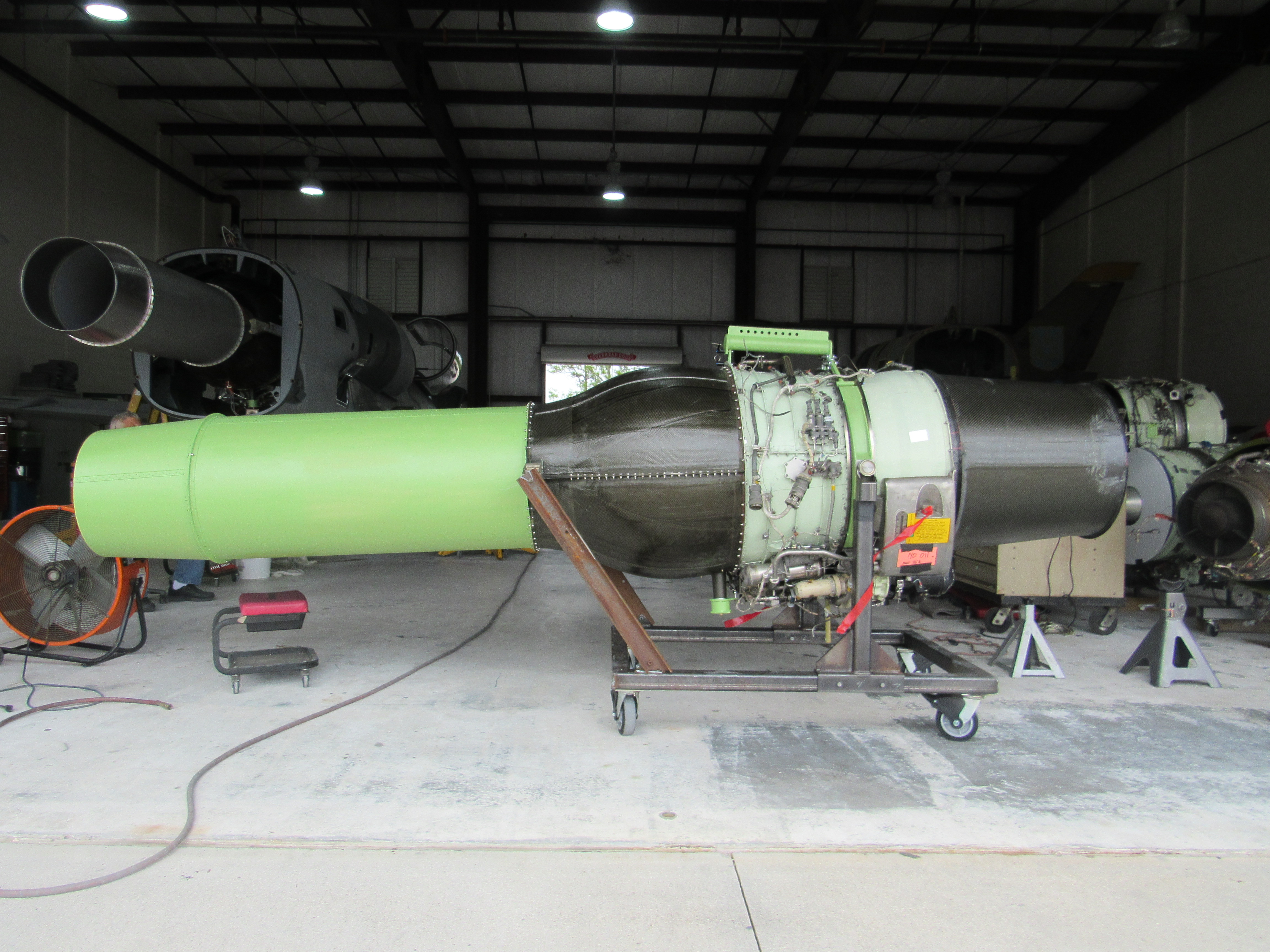
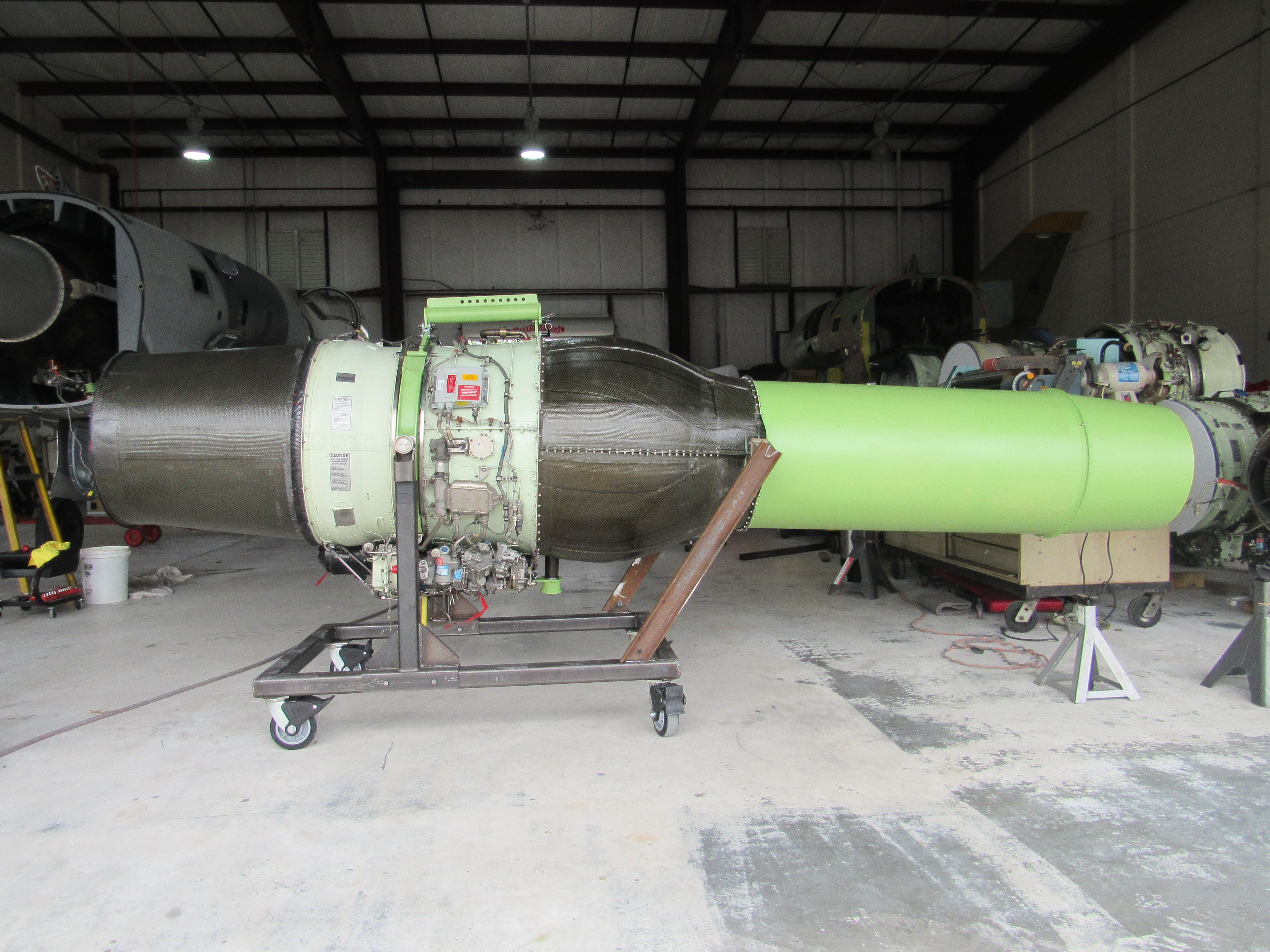
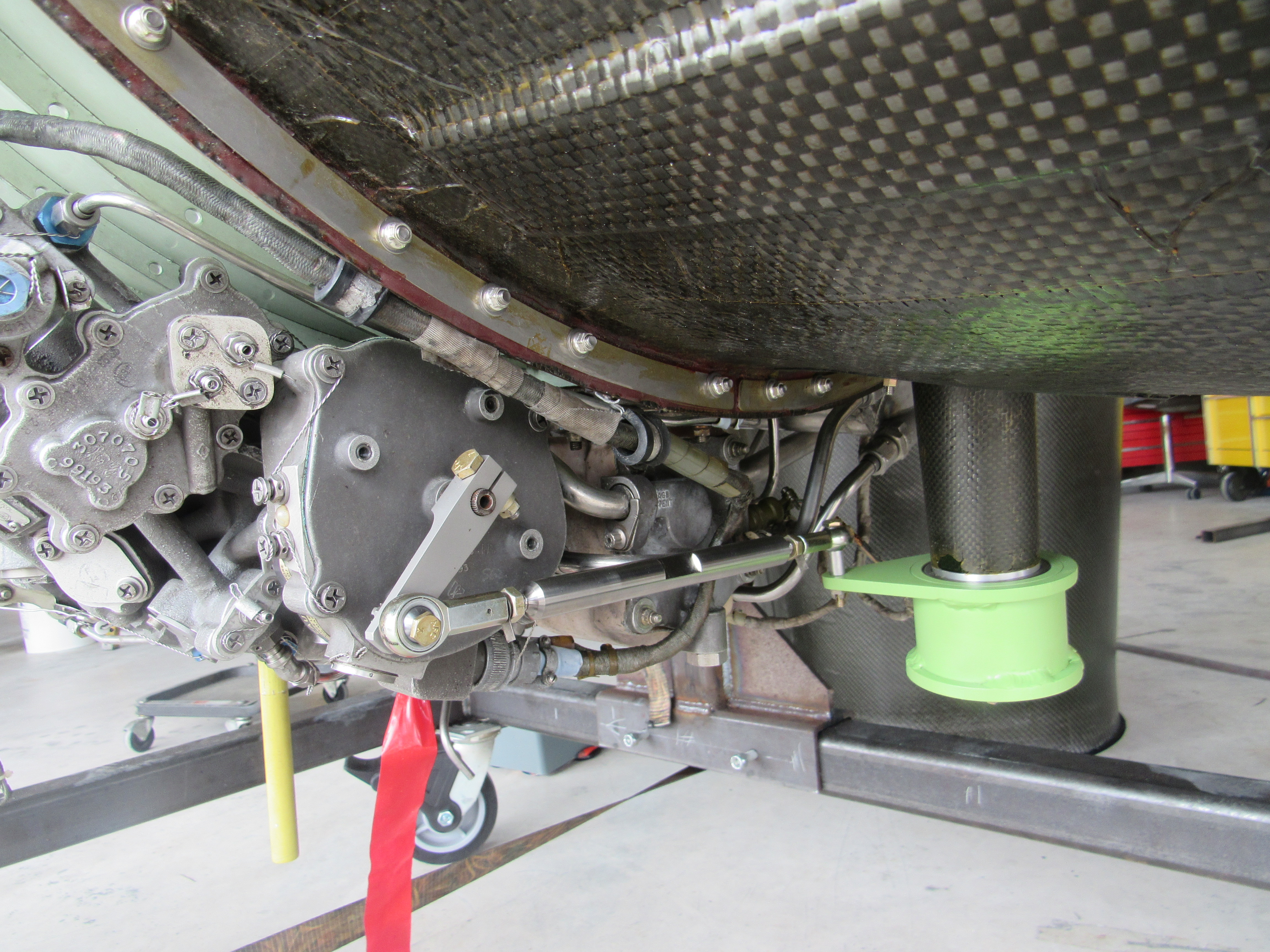
Included below are some pictures of our first customer delivery motor
assembly. Our normal engine stand was modified with new uprights to
accommodate the L39 front motor rollers and stays were added at the rear to
support the motor's rear mounts. Custom aluminum fabrications are given a
coat of Boeing's green epoxy primer. The throttle bellcrank shown connects
directly to a customer lengthened standard L39 longitudinal throttle rod.
Looking at the completed assembly on the stand, here are most (I'll add more
when I think of them) of the changes made and parts supplied working from the
front to the back.
Custom inlet cone to expand the L39's "Y" duct out to the 731-3's fan inlet -
front motor "velocity stack" carbon ring which acts to guide the inlet cone to
the front of the motor when the motor is rolled into the airframe -
Re-positioned starter/generator with shortened air inlet (screen added) - Ti or
Stainless front motor mounts using customer supplied front L39 rollers (we will
likely start producing these ourselves) - Oil
pressure adapter and standard oil pressure sensor (any acceptable 1/8" male NPT
sender can be used) - custom fuel Rf fuel flow pick up fitted to the original
Hawker/WestWind fuel flow turbine - jet core support hanger - custom composite
fan duct with integral throttle bellcrank mount tower - customer supplied L39
rear motor mounts (we may begin producing a custom mount if original equipment
items become scarce) - throttle bellcrank and mating push/pull rod to the fuel
control - custom fuel control actuation arm - patched green sheets to fill in
the unused HP bleed exit - modified HP bleed pipe exiting the combustion chamber
- exhaust exit tube - exhaust exit nozzle. Separate from the engine
is the N1/N2 signal conditioning box that generates waveforms acceptable to
experimental EFIS' like the Garmin G3X and Dynon Skyview. An N1 DEEC and
associated harness are supplied as well.
Specific Elements of the Installation Process
Bleed Air
Inverted Fuel Starter/Generator/RCR/GCU DEEC Airframe/G3X Interface
Check here for the current
"installation kit" contents or, what comes with a kit.
|
|
|
|
|
|
|
|
|
|
|
|
|

|
|
|
|
Freshly machined main motor mount rollers |
|
|
|
|
|
|
|
|

|
|
|
|
Trying one of the new rollers in the airframe |
|
|
|
|
|
|
|
|